

Description
S310-24PN4X
Overview
Huawei eKit SME Network switches are designed for the SMB market. They feature flexible Ethernet networking, diversified security control, and abundant management methods, and provide higher performance and richer service processing capabilities. Widely used in economic hotels, factories, small and medium-sized education, shelter hospitals, buildings Scenarios.
Table 4-107 Basic information about the S310-24PN4X
| Item | Details |
|---|---|
| Description | S310-24PN4X(24*10/100/1000/2.5GBASE-T ports(400W PoE+), 4*10GE SFP+ ports, built-in AC power) |
| Part Number | 98012534 |
| Model | S310-24PN4X |
| First supported version | V600R023C10SPC600 |
Components
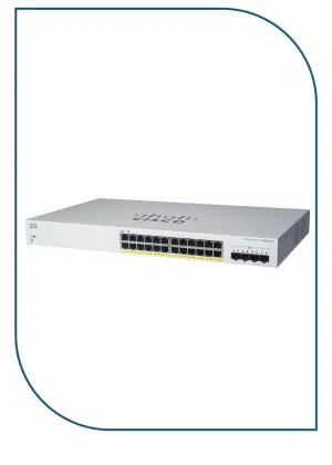
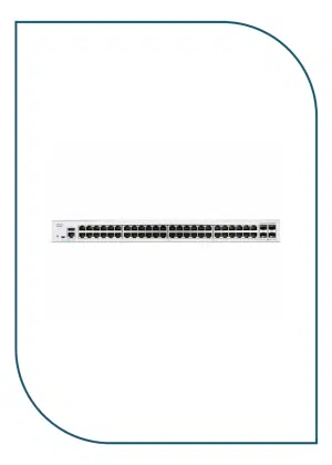
Figure 4-37 S310-24PN4X appearance

| 1 | Twenty-four 10M/100M/1000M/2.5GE BASE-T PoE+ ports (multi-GE ports) | 2 | Four 10GE SFP+ ports |
| 3 | One console port | 4 | One USB port |
| 5 | One MODE button | 6 | One RST button
NOTICE: To restore the factory settings and reset the device, hold down the button for at least 6 seconds. To reset the device, press the button. Resetting the device will cause service interruption. Exercise caution when you press the button. |
| 7 | Ground screw
NOTE: It is used with a ground cable.
|
8 | Jack for AC power cable locking strap
NOTE: The AC power cable locking strap is not delivered with the switch.
|
| 9 | AC socket
NOTE: It is used with an AC power cable. |
– | – |
Ports
Table 4-108 Maximum transmission distances of different cables on multi-GE ports
| Cable Type (6-a-1 Bundle) | Multi-GE Port (Different Rates) | |
|---|---|---|
| 10M/100M/1000M | 2.5GE | |
| Category 5e unshielded twisted pair (Cat5e UTP) | 100 m | 100 m |
| Category 5e shielded twisted pair (Cat5e STP) | 100 m | 100 m |
| Category 6 unshielded twisted pair (Cat6 UTP) | 100 m | 100 m |
| Category 6 shielded twisted pair (Cat6 STP) | 100 m | 100 m |
| Category 6A unshielded twisted pair (Cat6A U/UTP) | 100 m | 100 m |
| Category 6A foiled/unshielded twisted pair (Cat6A F/UTP) | 100 m | 100 m |
| Category 6A shielded twisted pair (Cat6A STP) | 100 m | 100 m |
| Category 7 twisted pair (Cat7) | 100 m | 100 m |

6-a-1 stands for the six-around-one cable bundle mode, with one cable in the center and six cables bundled evenly around it.
Table 4-109 Ports on the S310-24PN4X
| Port | Connector Type | Description | Available Components |
|---|---|---|---|
| 10M/100M/1G/2.5GE BASE-T PoE+ port (multi-GE port) | RJ45 | A 10M/100M/1G/2.5GE BASE-T PoE+ port (multi-GE port) sends and receives service data at 10 Mbit/s, 100 Mbit/s, 1 Gbit/s, or 2.5 Gbit/s.
The port supports the PoE function. |
If the 2.5 Gbit/s speed is required, the port must use an Ethernet cable of Cat5e or higher category. |
| 10GE SFP+ optical port | SFP+ | A 10GE SFP+ Ethernet optical port supports auto-sensing to 1000 Mbit/s. It sends and receives service data at 1000 Mbit/s or 10 Gbit/s. |
|
| Console port | RJ45 | The console port is connected to a console for on-site configuration. | Console cable |
| USB port | USB 2.0 Type A | The USB port can have a USB flash drive connected to upgrade the switch, or transfer configuration files or other files. The USB port can only connect to a USB flash drive that complies with USB 2.0.
USB flash drives from different vendors differ in model compatibility and drivers. If a USB flash drive cannot be used, try to replace it with another one from a mainstream vendor. |
USB flash drive |
Indicators and Buttons
Figure 4-38 Indicators on the Switch

Table 4-110 Description of indicators on the switch
| No. | Indicator | Name | Color | Status | Description |
|---|---|---|---|---|---|
| 1 | PWR | Power module indicator | – | Off | The switch is powered off. |
| Green | Steady on | The power supply is normal. | |||
| 2 | SYS | System status indicator | – | Off | The system is not running. |
| Green | Fast blinking | The system is starting. | |||
| Green | Steady on | During the system startup preparation phase, the SYS indicator is steady green, which lasts for a maximum of 30 seconds. | |||
| Green | Slow blinking | The system is running normally. | |||
| Red | Steady on | The system does not work normally after registration, or a fan alarm or a temperature alarm has been generated. | |||
| 3 | MST | Stack indicator | – | Off |
|
| Green | Steady on | The stack mode is selected. The switch is a standby or slave switch in a stack, and the service port indicators show the stack ID of the switch. | |||
| Green | Blinking |
|
|||
| 4 | PoE | PoE indicator | – | Off | The PoE mode is not selected. |
| Green | Steady on | The PoE mode is selected, and service port indicators show the PoE status of each port. | |||
| 5 | MODE | Mode switch button | – | – |
If you do not press the MODE button within 45 seconds, the service port indicators restore to the default mode. In this case, the PoE indicator is off. NOTE: Hold down the mode switch button for 6s and release it to start the web initial login mode. Either of the following situations will occur:
|
| 6 | – | Electrical service port indicator (one indicator for each port) | Arrowheads show the positions of ports. A down arrowhead indicates a port at the bottom, and an up arrowhead indicates a port at the top. | Meanings of service port indicators vary in different modes. For details, see Table 4-111 and Table 4-112.
NOTE: If a power failure occurs on a device’s PCB board, indicators of the last four GE or 10GE optical ports on the device’s front panel blink green cyclically at an interval of 1 second, with each i |
|