Home
Shop
Wishlist0

Huawei ekit S310-24ST4X SWITCH

S310-24ST4X(24*GE SFP ports, 8 of which are dual-purpose 10/100/1000 or SFP, 4*10GE SFP+ ports, built-in AC power)

WhatsApp Button Call for Price

Compare
Availability: In Stock
Brand:

Description

S310-24ST4X

Overview

Table 4-101 Basic information about the S310-24ST4X

Item Details
Description S310-24ST4X(24*GE SFP ports, 8 of which are dual-purpose 10/100/1000 or SFP, 4*10GE SFP+ ports, built-in AC power)
Part Number 98012532
Model S310-24ST4X
First supported version V600R023C10SPC600

Components

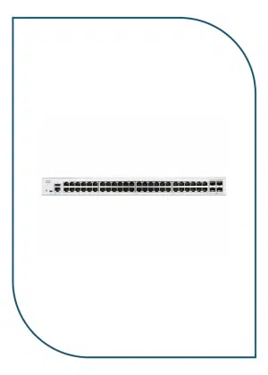
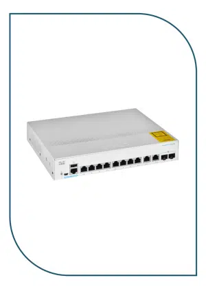
Figure 4-35 S310-24ST4X appearance
S310-24ST4X
1 One MODE button 2 Sixteen 100/1000BASE-X ports
3 Eight Combo ports (100/1000BASE-X optical ports and 10/100/1000BASE-T electrical ports)

NOTE:

In the default working mode, the electrical ports in the combo ports are available.

4 Four 10GE SFP+ ports
5 One console port 6 One ETH management port
7 One RST button

NOTICE:

To restore the factory settings and reset the device, hold down the button for at least 6 seconds.

To reset the device, press the button.

Resetting the device will cause service interruption. Exercise caution when you press the button.

8 Ground screw

NOTE:

It is used with a ground cable.
9 Jack for AC power cable locking strap

NOTE:

The AC power cable locking strap is not delivered with the switch.
10 AC socket

NOTE:

It is used with an AC power cable.

Ports

Table 4-102 Ports on the S310-24ST4X

Port Connector Type Description Available Components
100/1000BASE-X port SFP A 100/1000BASE-X port can send and receive data at 100/1000 Mbit/s.
Combo port (10/100/1000BASE-T + 100/1000BASE-X) RJ45/SFP A combo port refers to a pair of ports consisting of an optical Ethernet port and an electrical Ethernet port on the panel. Each combo port matches only one internal forwarding port. A combo port can be configured as an electrical port or an optical port, but only one port can be active at a time. When one port is active, the other port is shut down.
10GE SFP+ optical port SFP+ A 10GE SFP+ Ethernet optical port supports auto-sensing to 1000 Mbit/s. It sends and receives service data at 1000 Mbit/s or 10 Gbit/s.
Console port RJ45 The console port is connected to a console for on-site configuration. Console cable
ETH management port RJ45 You can connect a switch to a configuration terminal or network management workstation through the ETH management port to configure the switch locally or remotely. Ethernet cable

Indicators and Buttons

Figure 4-36 Indicators on the Switch
S310-24ST4X

Table 4-103 Description of indicators on the switch

No. Indicator Name Color Status Description
1 PWR Power module indicator Off The switch is powered off.
Green Steady on The power supply is normal.
2 SYS System status indicator Off The system is not running.
Green Fast blinking The system is starting.
Green Steady on During the system startup preparation phase, the SYS indicator is steady green, which lasts for a maximum of 30 seconds.
Green Slow blinking The system is running normally.
Red Steady on The system does not work normally after registration, or a fan alarm or a temperature alarm has been generated.
3 MST Stack indicator Off
  • If you are not changing the indicator mode (default): The switch is a standby or slave switch in a stack or the stacking function is not enabled on the switch.
  • If you are changing the indicator mode: The stack mode is not selected.
Green Steady on The stack mode is selected. The switch is a standby or slave switch in a stack, and the service port indicators show the stack ID of the switch.
Green Blinking
  • If you are not changing the indicator mode (default): The switch is the master switch in a stack or a standalone switch with the stacking function enabled.
  • If you are changing the indicator mode: The stack mode is selected. The switch is the master switch in a stack or a standalone switch, and the service port indicators show the stack ID of the master switch. After 45 seconds, the service port indicators automatically restore to the status mode.
4 MODE Mode switch button
  • When you press this button once, the service port indicators change to the stack mode and show the stack ID of the local switch.
  • When you press this button a second time, the service port indicators restore to the default mode and show the connection status and link activity of each service port.

If you do not press the MODE button within 45 seconds, the service port indicators restore to the default mode.

NOTE:

Hold down the mode switch button for 6s and release it to start the web initial login mode. Either of the following situations will occur:

  • If the switch has no configuration file, the system attempts to enter the web initial login mode.

    If the system enters the web initial login mode successfully, the MST mode indicator turn green and stay on for a maximum of 45 seconds.

  • If the login fails, check whether the device uses factory default settings.
5 CLOUD Cloud indicator

NOTE:

In versions earlier than V600R024C00, this indicator is reserved.

Off The management VLAN of the device does not obtain an IP address.
Blue Steady on The network is connected, and the management VLAN of the device obtains an IP address.
Blue Fast blinking The device is connecting to the cloud.
Blue Slow blinking The device is in the cloud management state.
6 Optical service port indicator (two indicators for each port) Each optical port has two single-color indicators. The one on the left is the ACT indicator (yellow), and the one on the right is the LINK indicator (green).

Arrowheads show the positions of ports. A down arrowhead indicates a port at the bottom, and an up arrowhead indicates a port at the top.

Meanings of service port indicators vary in different modes. For details, see Table 4-104 and Table 4-105.

NOTE:

If a power failure occurs on a device’s PCB board, indicators of the last four GE or 10GE optical ports on the device’s front panel blink green cyclically at an interval of 1 second, with each indicator illuminating for 0.25 seconds.


7 Electrical or optical service port indicator (one indicator for each port) Arrowheads show the positions of ports. A down arrowhead indicates a port at the bottom, and an up arrowhead indicates a port at the top.
8 ETH ETH port indicator Off The ETH port is not connected.
Green Steady on The ETH port is connected.
Green Blinking The ETH port is sending or receiving data.

Table 4-104 Description of service port indicators in different modes (one indicator for each port)

Display Mode Color Status Description
Default mode Off The port is not connected or has been shut down.
Green Steady on A link has been established on the port.
Green Blinking The port is sending or receiving data.

Table 4-105 Description of service port indicators in different modes (two indicators for each port)

Display Mode Color Status Description
Default mode (LINK indicator) Off The port is not connected or has been shut down.
Green Steady on A link has been established on the port.
Default mode (ACT indicator) Off The port is not connected or has been shut down, or no data is transmitted or received.
Yellow Blinking The port is sending or receiving data.
MST stack mode (LINK indicator) Off Port indicators do not show the stack ID of the switch.
Green Steady on The switch is not the master switch in a stack.

If the indicator of a port is steady on, the number of this port is the stack ID of the switch.

Green Blinking The switch is the master switch in a stack.

If the indicator of a port is blinking, the number of this port is the stack ID of the switch.

MST stack mode (ACT indicator) Off Port indicators do not show the stack ID of the switch.

Power Supply System

The switch has a built-in AC power module and does not support pluggable power modules.

Heat Dissipation System

The switch has two built-in fans for forced air cooling. Air flows in from the left side and front panel, and exhausts from the right side.

When working properly at a normal temperature, the device meets the desktop-class noise requirements. However, the fan speed may be high and the noise may be loud during device startup.

S310-24ST4X

This figure only shows the airflow direction and does not depict the actual device.

Technical Specifications

Table 4-106 Technical specifications of the S310-24ST4X

Item Specification
Dimensions without packaging (H x W x D) [mm(in.)] Basic dimensions (excluding the parts protruding from the body): 43.6 mm x 442.0 mm x 220.0 mm (1.72 in. x 17.4 in. x 8.66 in.)

Maximum dimensions (the depth is the distance from ports on the front panel to the parts protruding from the rear panel): 43.6 mm x 442.0 mm x 227.0 mm (1.72 in. x 17.4 in. x 8.94 in.)

Dimensions with packaging (H x W x D) [mm(in.)] 90.0 mm x 550.0 mm x 360.0 mm (3.54 in. x 21.65 in. x 14.17 in.)
Chassis height [U] 1 U
Weight without packaging [kg(lb)] 2.9 kg (6.39 lb)
Weight with packaging [kg(lb)] 3.55 kg (7.83 lb)
Typical power consumption [W] 32.6 W
Typical heat dissipation [BTU/hour] 111.23 BTU/hour
Maximum power consumption [W] 41.7 W
Maximum heat dissipation [BTU/hour] 142.28 BTU/hour
Static power consumption [W] 17.57 W
MTBF [years] 47.39 years
MTTR [hours] 2 hours
Availability > 0.99999
Noise at normal temperature (acoustic power) [dB(A)] 38.1 dB(A)
Noise at normal temperature (acoustic pressure) [dB(A)] 26.1 dB(A)
Number of card slots 0
Number of power slots 0
Number of fans modules 2
Redundant power supply Not supported
Long-term operating temperature [°C(°F)] -5°C to +50°C (23°F to 122°F) at an altitude of 0-1800 m (0-5905.44 ft.)
Restriction on the operating temperature variation rate [°C(°F)] When the altitude is 1800–5000 m (5906–16404 ft.), the highest operating temperature reduces by 1°C (1.8°F) every time the altitude increases by 220 m (722 ft.).

Devices cannot start when the temperature is lower than 0°C (32°F).

Storage temperature [°C(°F)] –40°C to +70°C (–40°F to +158°F)
Long-term operating relative humidity [RH] 5% RH to 95% RH (non-condensing)
Long-term operating altitude [m(ft.)] 0–5000 m (0–16404 ft.)
Storage altitude [m(ft.)] 0-5000 m (0-16404 ft.)
Power supply mode AC built-in
Rated input voltage [V]
  • AC input: 100 V AC to 240 V AC; 50/60 Hz
  • High-voltage DC input: 110 V DC to 250 V DC
Input voltage range [V]
  • AC input: 90 V AC to 264 V AC; 47 Hz to 63 Hz
  • High-voltage DC input: 88 V DC to 300 V DC
Maximum input current [A] 2 A
Memory 2 GB
Flash memory Physical space: 1 GB
Console port RJ45
Eth Management port Supported
USB Not supported
RTC Not supported
RPS input Not supported
Power supply surge protection [kV] Differential mode: ±6 kV; common mode: ±6 kV
Ingress protection level (dustproof/waterproof) IP20
Types of fans Built-in
Heat dissipation mode Air cooling for heat dissipation, intelligent fan speed adjustment
Airflow direction Air intake from left and front, air exhaustion from right
PoE Not supported
Certification EMC certification

Safety certification

Manufacturing certification

Product has been added to your cart