
 + 8 x GE Combo+ 2 x GE, 100 Users (USG6000E-S13-AC)")
 + 8 x GE Combo+ 2 x GE, 100 Users (USG6000E-S13-AC)")
 + 8 x GE Combo+ 2 x GE, 100 Users (USG6000E-S13-AC)")
 + 8 x GE Combo+ 2 x GE, 100 Users (USG6000E-S13-AC)")
 + 8 x GE Combo+ 2 x GE, 100 Users (USG6000E-S13-AC)")
Description
USG6000E-S13-AC
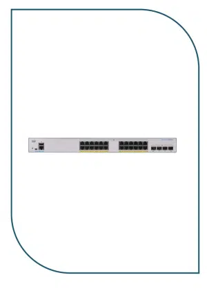
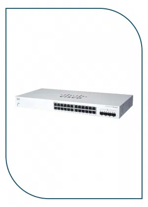
The Huawei USG6000E-S13-AC is a next-generation enterprise firewall designed to deliver secure, high-performance network protection for small to medium-sized businesses. It integrates advanced security features with flexible high-speed connectivity to support up to 100 users.
Key features:
-
Interfaces: 2 × 10GE SFP+, 8 × GE Combo, 2 × GE
-
User capacity: Up to 100 users
-
Integrated AC power supply
-
Advanced firewall and VPN capabilities
-
Intrusion prevention (IPS) and attack defense
-
Application control and traffic management
-
High reliability and stable performance
-
Ideal for enterprise edge security and branch offices
| Model | USG6000E-S13-AC Firewall |
|---|---|
| CPU | 1 CPU, 4 cores/CPU, up to 1.4 GHz |
| Internal Memory | 4 GB DDR4 |
| Dimensions | 44.2 x 42 x 4.36 cm |
| Weight | 7.93 kg |
| Technical Specifications | |
| Installation Type | Rack,Work bench |
| Cabinet installation standard | Cabinet with a depth of 600 mm or above |
| Wide [mm] | 442 mm |
| Depth [mm] | 420 mm |
| Height [mm] | 43.6 mm |
| Chassis height [U] | 1 |
| Weight without packaging [kg(lb)] | 5.95 (13.12) |
| Weight with packaging [kg(lb)] | 7.93 (17.48) |
| Maximum power consumption [W] | 45.3 |
| Maximum heat dissipation [BTU/hour] | 154.4 |
| Heat dissipation mode | Absorbing cold air into the device |
| Power supply mode | Built-in AC |
| Rated input voltage [V] | 100 V to 240 V, 50 Hz/60 Hz |
| Input voltage range [V] | 90 V to 290 V, 47 Hz to 63 Hz |
| CPU | 1 CPU, 4 cores/CPU, up to 1.4 GHz |
| Memory | DDR4 4 GB |
| NOR Flash | 64MB |
| NAND Flash | 2 GB |
| Hard disk | Optional. M.2 SSD (64GB/240GB/960GB), hot-swappable. |
| Redundant power supply | Dual power modules can be purchased to form 1+1 redundancy backup. |
| Number of power modules | 1 |
| Number of fan modules | 1 |
| Types of fans | Pluggable |
| Airflow direction | Air flows in from the front panel and exhausts from the rear panel. |
| Long-term operating temperature [°C(°F)] | 0°C to 45°C |
| Storage temperature [°C(°F)] | -40°C to 70°C |
| Long-term operating relative humidity [RH] | 5% RH to 95% RH, non-condensing |
| Storage relative humidity [RH] | 5% RH to 95% RH, non-condensing |
| Long-term operating altitude [m(ft.)] | 0 m to 5000 m |
| Storage altitude [m(ft.)] | 0 m to 5000 m |
| MTBF [year] | 68.98 |
| MTTR [hour] | 2 |
| Console port | RJ45 |
| Eth Management port | RJ45 |