
, 4*10GE SFP+ ports, built-in AC power) Switch (S310-24P4X)")
, 4*10GE SFP+ ports, built-in AC power) Switch (S310-24P4X)")
Description
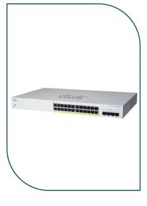
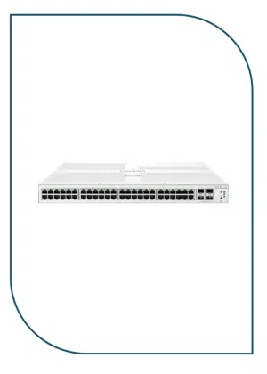
The Huawei S310-24P4X is a managed Layer-2/Layer-2+ PoE network switch designed for enterprise, SMB, and campus networks that need both data connectivity and power over Ethernet. It offers 24 Gigabit Ethernet PoE+ ports to connect and power devices like IP cameras, wireless access points, and VoIP phones over a single cable.
For high-speed backbone connections, it includes 4 × 10 GE SFP+ uplink ports, giving you fast fiber or copper uplinks to core switches or servers. The switch has a built-in AC power supply with a 400 W PoE budget, and delivers reliable performance with features like VLAN, QoS, stacking, and advanced security.
Key Specifications
Ports
-
24 × 10/100/1000 BASE-T PoE+ ports (supports IEEE 802.3af/at PoE).
-
4 × 10 GE SFP+ uplinks (10 Gb/s capable).
-
1 × RJ45 console port for local management.
Performance
-
Switching capacity: 128 Gbps.
-
Packet forwarding rate: ~96 Mpps.
PoE
-
PoE+ support: yes (802.3af/at).
-
Total PoE power budget: up to 400 W.
Power & Cooling
-
Built-in AC power supply (100–240 VAC).
-
2 internal fans for active cooling.
-
Max power consumption: ~485.9 W with full PoE load.
Management & Features
-
Managed Layer-2/Layer-2+ features: VLAN, QoS, link aggregation (LACP), DHCP Snooping, STP/RSTP, security controls, etc.
-
Support for Web GUI, CLI, SNMP, Telnet/SSH, cloud/eKit app.
-
iStack stacking (up to 4 switches).
Physical & Environment
-
1U rack mount chassis (43.6 × 442 × 220 mm).
-
Weight: ~2.92 kg (no packaging).
-
Operating temp: –5 °C to +50 °C.
-
Humidity: 5 %–95 % non-condensing.