


Description
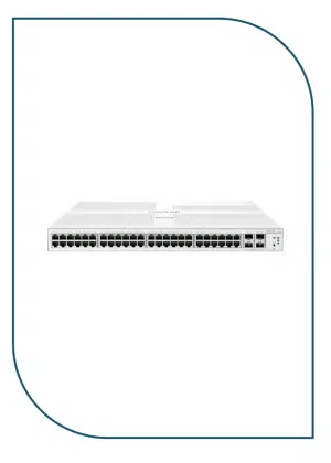
S310-48P4X
overview
Table 4-73 Basic information about the S310-48P4X
| Item | Details |
|---|---|
| Description | S310-48P4X (48*10/100/1000BASE-T ports(380W PoE+), 4*10GE SFP+ ports, built-in AC power) |
| Part Number | 98012385 |
| Model | S310-48P4X |
| First supported version | V600R023C00 |
Components
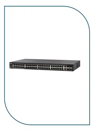
Figure 4-26 S310-48P4X appearance

| 1 | Forty-eight 10/100/1000BASE-T PoE+ ports | 2 | Four 10GE SFP+ ports |
| 3 | One console port | 4 | One MODE button |
| 5 | One RST button
NOTICE: To restore the factory settings and reset the device, hold down the button for at least 6 seconds. To reset the device, press the button. Resetting the device will cause service interruption. Exercise caution when you press the button. |
6 | Ground screw
NOTE: It is used with a ground cable.
|
| 7 | Jack for AC power cable locking strap
NOTE: The AC power cable locking strap is not delivered with the switch.
|
8 | AC socket
NOTE: It is used with an AC power cable. |
Ports
Table 4-74 Ports on the S310-48P4X
| Port | Connector Type | Description | Available Components |
|---|---|---|---|
| 10/100/1000BASE-T port | RJ45 | A 10/100/1000BASE-T Ethernet electrical port sends and receives service data at 10/100/1000 Mbit/s. | Ethernet cable |
| 10GE SFP+ port | SFP+ | A 10GE SFP+ Ethernet optical port supports auto-sensing to 1000 Mbit/s. It sends and receives service data at 1000 Mbit/s or 10 Gbit/s. |
|
| Console port | RJ45 | The console port is connected to a console for on-site configuration. | Console cable |
Indicators and Buttons
Figure 4-27 Indicators on the Switch

Table 4-75 Description of indicators on the switch
| No. | Indicator | Name | Color | Status | Description |
|---|---|---|---|---|---|
| 1 | PWR | Power module indicator | – | Off | The switch is powered off. |
| Green | Steady on | The power supply is normal. | |||
| 2 | SYS | System status indicator | – | Off | The system is not running. |
| Green | Fast blinking | The system is starting. | |||
| Green | Steady on | During the system startup preparation phase, the SYS indicator is steady green, which lasts for a maximum of 30 seconds. | |||
| Green | Slow blinking | The system is running normally. | |||
| Red | Steady on | The system does not work normally after registration, or a fan alarm or a temperature alarm has been generated. | |||
| 3 | MST | Stack indicator | – | Off |
|
| Green | Steady on | The stack mode is selected. The switch is a standby or slave switch in a stack, and the service port indicators show the stack ID of the switch. | |||
| Green | Blinking |
|
|||
| 4 | PoE | PoE indicator | – | Off | The PoE mode is not selected. |
| Green | Steady on | The PoE mode is selected, and service port indicators show the PoE status of each port. | |||
| 5 | MODE | Mode switch button | – | – |
If you do not press the MODE button within 45 seconds, the service port indicators restore to the default mode. In this case, the PoE indicator is off. |
| 6 | – | Electrical service port indicator (one indicator for each port) | Arrowheads show the positions of ports. A down arrowhead indicates a port at the bottom, and an up arrowhead indicates a port at the top. | Meanings of service port indicators vary in different modes. For details, see Table 4-76 and Table 4-77.
NOTE: If a power failure occurs on a device’s PCB board, indicators of the last four GE or 10GE optical ports on the device’s front panel blink green cyclically at an interval of 1 second, with each indicator illuminating for 0.25 seconds.
|
|
| 7 | – | Optical service port indicator (two indicators for each port) | Each optical port has two single-color indicators. The one on the left is the ACT indicator (yellow), and the one on the right is the LINK indicator (green).
Arrowheads show the positions of ports. A down arrowhead indicates a port at the bottom, and an up arrowhead indicates a port at the top. |
||
| 8 | CLOUD | Cloud indicator | – | Off | The device is not in the cloud management state. |
| Blue | Fast blinking | The device is connecting to the cloud. | |||
| Blue | Slow blinking | The device is in the cloud management state. | |||
| Blue | Steady on | The network is connected, and the management VLAN of the device obtains an IP address. | |||
Table 4-76 Description of service port indicators in different modes (one indicator for each port)
| Display Mode | Color | Status | Description |
|---|---|---|---|
| Default mode | – | Off | The port is not connected or has been shut down. |
| Green | Steady on | A link has been established on the port. | |
| Green | Blinking | The port is sending or receiving data. | |
| MST stack mode | – | Off | Port indicators do not show the stack ID of the switch. |
| Green | Steady on | The switch is not the master switch in a stack.
If the indicator of a port is steady on, the number of this port is the stack ID of the switch. |
|
| Green | Blinking | The switch is the master switch in a stack.
If the indicator of a port is blinking, the number of this port is the stack ID of the switch. |
|
| PoE mode | – | Off | The port is not providing power to a powered device (PD). |
| Green | Steady on | The port is providing power to a PD. | |
| Green | Blinking | The power of the PD connected to the port exceeds the power capacity of the port or the power threshold configured on the port. Alternatively, the PD does not comply with IEEE standards. |
Table 4-77 Description of service port indicators in different modes (two indicators for each port)
| Display Mode | Color | Status | Description |
|---|---|---|---|
| Default mode (LINK indicator) | – | Off | The port is not connected or has been shut down. |
| Green | Steady on | A link has been established on the port. | |
| Default mode (ACT indicator) | – | Off | The port is not connected or has been shut down, or no data is transmitted or received. |
| Yellow | Blinking | The port is sending or receiving data. |
Reviews
There are no reviews yet.