Description
AR730
Within the Huawei NetEngine AR700 series, there are two main models : NetEngine AR720 and NetEngine AR730.
Table 3-17 Basic information about the AR730
Item | Details |
---|---|
Description | AR730, 2*GE combo WAN, 1*10GE(SFP+) WAN, 8*GE LAN, 1*GE combo LAN, 2*USB 2.0, 2*SIC |
Part Number | 02354GBM-001 |
Model | AR730 |
First supported version | V300R022C00 |
Supported Patch Version |
If you want to downgrade a device running V300R022C10SPC100 or a later version to V300R019C10SPC600, V300R019C13SPC200, or V300R021C00SPC200 after the component upgrade, downgrade the device to V300R022C00SPC100 first. If you want to downgrade a device to a version earlier than V300R022C00SPC100 after the component upgrade, set the patch for next startup to the start patch of the target version or a later patch. ( start patch of V300R019C10SPC600 is V300R019SPH380; the start patch of V300R019C13SPC200 is V300R019SPH380; the start patch of V300R021C00SPC200 is V300R021SPH180.) |
Remarks | When configuring cards, ensure that the total power of the configured cards does not exceed 37 W or contact technical support engineers to obtain more suggestions. |
AR730 Appearance
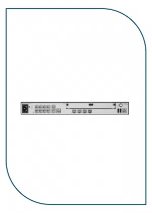
Figure 3-11 Appearance of the AR730
This model has had changes to its appearance and branding, and devices delivered over different periods may have different appearances but have no differences in functions.
Components
Figure 3-12 Components of the AR730
1. Product model silkscreen |
2. LAN interfaces: eight GE electrical interfaces |
3. WAN interfaces: two GE combo interfaces |
4. Two SIC slots |
5. Ground point |
6. AC power jack |
7. Jack for power cable locking strap NOTE: Insert a power cable locking strap in this jack to secure the power cable. |
8. RESET button NOTE: This button is used to reset the router.
Resetting the router will interrupt services. Exercise caution when deciding to press this button. |
9. LAN interfaces: GE combo interface |
10. WAN interface: one 10GE optical interface |
11. USB interface 2.0 (host) |
12. USB interface 2.0 (host) |
13. Console interface |
– |
– |
Slot Layout
Table 3-18 Slots on the AR730
Slot Type | Slot ID | Slot Direction | Remarks |
---|---|---|---|
SIC | 1 | Transverse | Slot 1 and slot 2 are combined into new slot 2 (WSIC). |
SIC | 2 | Transverse | Slot 1 and slot 2 are combined into new slot 2 (WSIC) . |
Ports
Table 3-19 Ports on the AR730
Port | Connector Type | Description | Available Components |
---|---|---|---|
Console interface | RJ45 |
The console interface can connect to an operation terminal for onsite configuration.
|
|
LAN interfaces: eight GE electrical interfaces | RJ45 |
A GE electrical interface (10/100/1000 Mbit/s auto-sensing) transmits and receives services at 10 Mbit/s, 100 Mbit/s, or 1000 Mbit/s.
NOTE: GE0 is a management interface and is used for web-based management and email-based deployment. All LAN-side GE interfaces can be configured as WAN-side interfaces. |
|
LAN interfaces: GE combo interface |
GE electrical interface: RJ45 GE optical interface: LC/PC |
A GE combo interface consists of an optical Ethernet interface and an electrical Ethernet interface on the panel. The two interfaces have only one internal forwarding interface. The electrical and optical interfaces are multiplexed, and only either of them can work at a time. When either of the Ethernet interfaces is working, the other interface is shut down.
NOTE: By default, a combo interface works in auto mode and automatically works as an optical or electrical interface. GE8 is the Boot ROM management network port on a device and is used to upgrade the device software through the Boot ROM menu. All GE combo LAN interfaces can be configured as WAN interfaces. |
The following optical modules are supported: GPON&EPON Optical Modules (Available in V300R023C00 and Later Versions) GE SFP Copper Modules (Available in V300R023C00 and Later Versions) |
WAN interfaces: two GE combo interfaces |
GE electrical interface: RJ45 GE optical interface: LC/PC |
A GE combo interface consists of an optical Ethernet interface and an electrical Ethernet interface on the panel. The two interfaces have only one internal forwarding interface. The electrical and optical interfaces are multiplexed, and only either of them can work at a time. When either of the Ethernet interfaces is working, the other interface is shut down.
NOTE: By default, a combo interface works in auto mode and automatically works as an optical or electrical interface. |
The following optical modules are supported: GPON&EPON Optical Modules (Available in V300R023C00 and Later Versions) GE SFP Copper Modules (Available in V300R023C00 and Later Versions) |
WAN interface: one 10GE optical interface | LC/PC |
The 10GE optical interfaces (1/10 Gbit/s auto-sensing) can work in GE mode and can transmit and receive service traffic at 1 Gbit/s or 10 Gbit/s.
|
Optical module The following optical modules are supported: GPON&EPON Optical Modules (Available in V300R023C00 and Later Versions) GE SFP Copper Modules (Available in V300R023C00 and Later Versions) 10GE SFP+ Copper Modules (Available in V300R023C10 and Later Versions) |
USB 2.0 ports (Host): two USB 2.0 ports | USB 2.0 Type A |
A USB 2.0 interface provides up to 480 Mbit/s upload and download rates.
|
USB 2.0-compliant USB flash drive |
Indicators and Buttons
Figure 3-14 Indicators and buttons on the AR730
1. From top to bottom:
|
2. GE electrical interface indicators (LAN) |
3. GE electrical interface indicators (WAN) |
4. GE optical interface indicator (LAN) |
5. GE optical interface indicator (WAN) |
6. 10GE optical interface indicator (WAN) |
7. ACT (USB) indicator |
– |
– |
Table 3-20 Indicators on the AR730
Silkscreen | Name | Color | Status | Description |
---|---|---|---|---|
PWR | PWR indicator | Green | Steady on | The device is powered by the built-in power module normally. |
– | Off | The device is not powered on. | ||
SYS | SYS indicator | Green | Slow blinking | The system is running properly. |
Green | Fast blinking | The system is being powered on or restarted. | ||
Red | Steady on | A fault that affects services has occurred. The fault cannot be rectified automatically and requires manual intervention. | ||
– | Off | The system software is not running or is resetting. | ||
iNET | iNET indicator | Green | Steady on | The network service has been established. |
– | Off | The network service is unavailable. | ||
CTRL | CTRL indicator | Green | Steady on | The device has been connected to the controller. |
– | Off | The device is not connected to the controller. | ||
– | GE electrical interface indicators (LAN) | Green | Steady on | A link has been established. |
Green | Off | No link is established. | ||
Yellow | Blinking | Data is being transmitted or received. | ||
Yellow | Off | No data is being transmitted or received. | ||
– | GE electrical interface indicators (WAN) | Green | Steady on | A link has been established. |
Green | Off | No link is established. | ||
Yellow | Blinking | Data is being transmitted or received. | ||
Yellow | Off | No data is being transmitted or received. | ||
– | GE optical interface indicator (LAN) | Green | Steady on | A link has been established. |
Green | Blinking | Data is being transmitted or received. | ||
– | Off | No link is established. | ||
– | GE optical interface indicator (WAN) | Green | Steady on | A link has been established. |
Green | Blinking | Data is being transmitted or received. | ||
– | Off | No link is established. | ||
– | 10GE optical interface indicator (WAN) | Green | Steady on | A link has been established. |
Green | Blinking | Data is being transmitted or received. | ||
– | Off | No link is established. | ||
– | ACT (USB) indicators | Green | Steady on | The system has been upgraded or configured using a USB flash drive. |
Green | Blinking | The system is being upgraded or configured using a USB flash drive. | ||
Red | Steady on | The system fails to be upgraded or configured using a USB flash drive. | ||
– | Off | No USB flash drive is connected, the USB interface has failed, or the indicator has failed. |
Table 3-21 Buttons on the AR730
Silkscreen | Name | Description |
---|---|---|
RESET | RESET button |
This button is used to reset the router.
Resetting the router will interrupt services. Exercise caution when deciding to press this button. |
AR730 Technical Specifications
Table 3-22 Technical specifications of the AR730
Item | Specification |
---|---|
Installation type |
|
Chassis height [U] | 1 U |
Dimensions without packaging (H x W x D) [mm(in.)] |
|
Dimensions with packaging (H x W x D) [mm(in.)] | 90 mm x 570 mm x 390 mm (3.54 in. x 22.44 in. x 15.35 in.) |
Weight with packaging [kg(lb)] | 4.6 kg (10.12 lb) |
Weight without packaging [kg(lb)] | 3.2 kg (7.04 lb) |
CPU | 1.4 GHz, 4 Cores |
Memory | 4 GB |
NAND Flash | 1 GB |
Console port | RJ45 |
RTC | Supported |
LAN ports | 8 x GE electrical, 1 x GE combo |
WAN ports | 2 x GE combo, 1 x 10GE optical (SFP+) |
Number of service board slots | 2 |
MIC slots (default/maximum) | 0/0 |
SIC slots (default/maximum) | 2/2 |
WSIC slots (default/maximum) | 0/1 |
XSIC slots (default/maximum) | 0/0 |
Redundant MPUs | Not supported |
RPS input | Not supported |
PoE | Not supported |
IP rating | IP20 |
MTBF [years] | 30.05 years |
MTTR [hours] | 2 hours |
Availability | 0.9999924012 |
Typical power consumption [W] | 28 W |
Maximum power consumption [W] | 33 W |
Power supply mode | AC built-in |
Number of power modules | 1 |
Rated input voltage [V] | 100 V to 240 V, 50 Hz/60 Hz |
Input voltage range [V] | 90 V to 264 V, 47 Hz to 63 Hz |
Maximum input current [A] | 2 A |
Maximum output power [W] | 70 W |
Redundant power supply | Not supported |
Type of fans | Built-in |
Number of fan modules | 1 |
Heat dissipation mode | Air cooling |
Airflow | Left-to-right airflow |
Noise at normal temperature (acoustic power) [dB(A)] | 52.3 dB(A) |
Long-term operating temperature [°C(°F)] |
0°C to 45°C (32°F to 113°F) NOTE: When the altitude is 1800–5000 m (5906–16404 ft.), the highest operating temperature reduces by 1°C (1.8°F) every time the altitude increases by 220 m (722 ft.). |
Long-term operating relative humidity [RH] | 5% RH to 95% RH, non-condensing |
Long-term operating altitude [m(ft.)] | < 5000 m (16404.2 ft.) |
Storage temperature [°C(°F)] | -40°C to +70°C (-40°F to +158°F) |
Overtemperature alarm | Supported |