Description
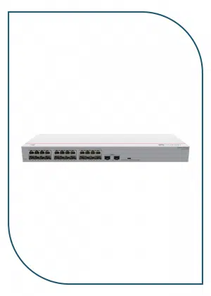
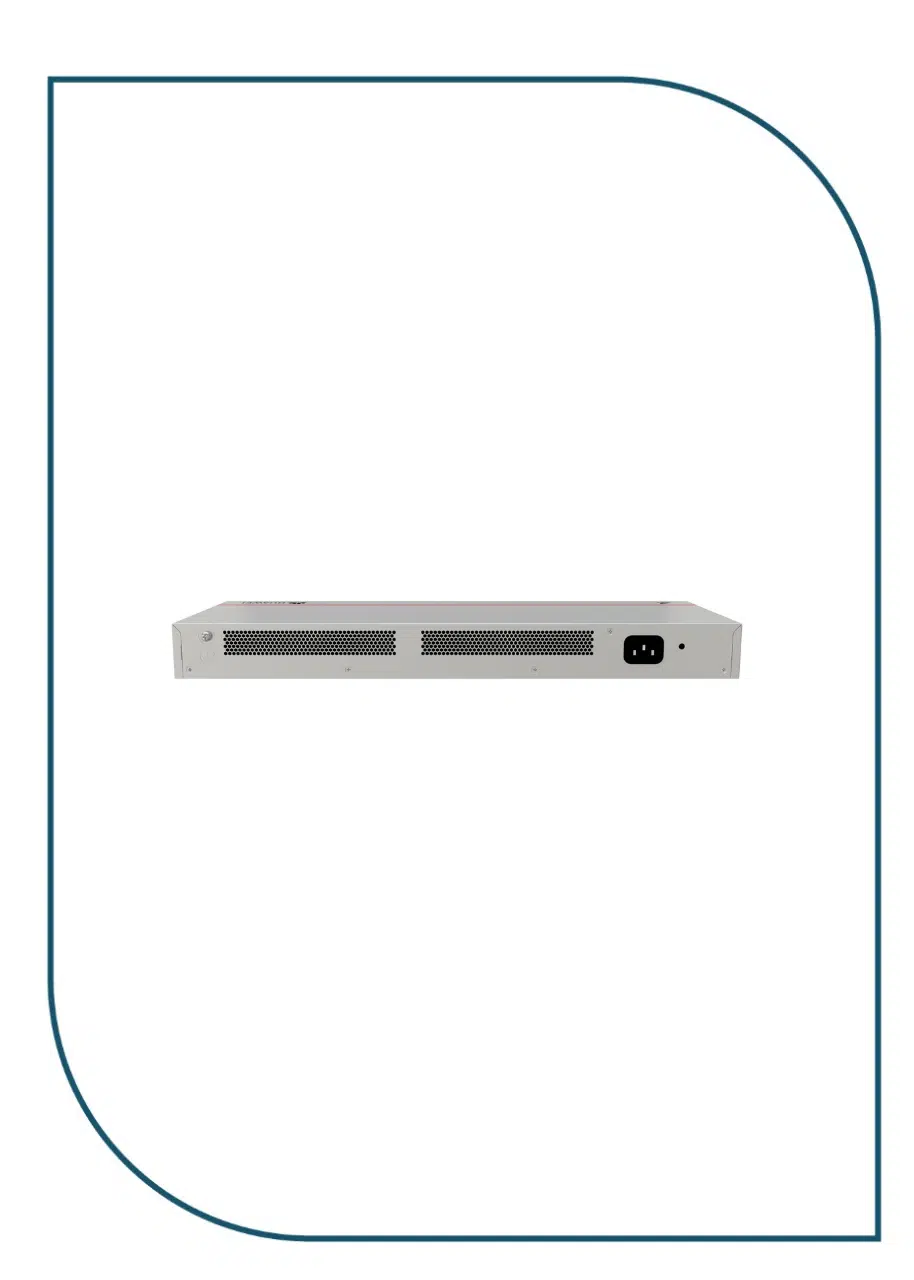
S110-24T2SR
Components
| Item | Specification |
|---|---|
| Dimensions without packaging (H x W x D) [mm(in.)] | Basic dimensions (excluding the parts protruding from the body): 43.6 mm x 442.0 mm x 160.0 mm (1.72 in. x 17.40 in. x 6.30 in.)
Maximum dimensions (the depth is the distance from ports on the front panel to the parts protruding from the rear panel): 43.6 mm x 442.0 mm x 167.0 mm (1.72 in. x 17.40 in. x 6.57 in.) |
| Dimensions with packaging (H x W x D) [mm(in.)] | 90.0 mm x 550.0 mm x 260.0 mm (3.54 in. x 21.65 in. x 10.24 in.) |
| Chassis height [U] | 1 U |
| Chassis material | Metal |
| Weight without packaging [kg(lb)] | 1.8 kg (3.97 lb) |
| Weight with packaging [kg(lb)] | 2.3 kg (5.07 lb) |
| Typical power consumption [W] | 16 W |
| Typical heat dissipation [BTU/hour] | 54.6 BTU/hour |
| Maximum power consumption [W] | 17 W |
| Maximum heat dissipation [BTU/hour] | 58 BTU/hour |
| Static power consumption [W] | 5 W |
| MTBF [years] | 76.10 years |
| Availability | > 0.99999 |
| Noise at normal temperature (acoustic power) [dB(A)] | Noise-free (no fans), < 30 |
| Noise at normal temperature (acoustic pressure) [dB(A)] | Noise-free (no fans), < 20 |
| Number of card slots | 0 |
| Number of power slots | 0 |
| Number of fans modules | 0 |
| Working mode |
|
| MAC address entry | 8K |
| Redundant power supply | Not supported |
| Long-term operating temperature [°C(°F)] | 0°C to 40°C (32°F to 104°F) at an altitude of 0-1800 m (0-5906 ft.) |
| Restriction on the operating temperature variation rate [°C(°F)] | When the altitude is 1800-5000 m (5906-16404 ft.), the highest operating temperature reduces by 1°C (1.8°F) every time the altitude increases by 220 m (722 ft.). |
| Storage temperature [°C(°F)] | –40°C to +70°C (–40°F to +158°F) |
| Long-term operating relative humidity [RH] | 5% RH to 95% RH, non-condensing |
| Long-term operating altitude [m(ft.)] | 0–5000 m (0–16404 ft.) |
| Storage altitude [m(ft.)] | 0-5000 m (0-16404 ft.) |
| Power supply mode | AC built-in |
| Rated input voltage [V] | AC input: 100–240 V AC; 50/60 Hz |
| Input voltage range [V] | AC input: 90 V AC to 264 V AC; 45 Hz to 65 Hz |
| Maximum input current [A] | 0.8 A |
| Memory | – |
| Flash memory | – |
| Console port | Not supported |
| Eth Management port | Not supported |
| USB | Not supported |
| RTC | Not supported |
| RPS input | Not supported |
| Service port surge protection [kV] | Common mode: ±1 kV |
| Power supply surge protection [kV] | Differential mode: ±6 kV; common mode: ±6 kV |
| Ingress protection level (dustproof/waterproof) | IP20 |
| Types of fans | None |
| Heat dissipation mode | Natural heat dissipation |
| Airflow direction | – |
| PoE | Not supported |
| Certification | EMC certification
Safety certification Manufacturing certification |


